During the packaging process, the product is typically fed to the dosing device to be dispensed using a feed mechanism on the packaging machine. The product is then poured into the packaging container and subsequently packaged.
This section introduces the feeding device typically used in packaging machines and the vacuum pump used in vacuum packaging machines. For information on the quantitative dosing device, please refer to the chapter on the loading machine. The chapter on the packaging machine also introduces the operating principles and several typical structural designs of the packaging container, the packaging material feeder, the filling and dispensing device, and the wrapping and packaging device.
Feeding device
The function of the packaging item feeder is to feed the items to be packaged—which are stored in the hopper—to the item dosing device, in order to dose the items according to the requirements of the packaging process. The other components of the packaging machine then carry out the packaging operation.
The feeding system for packaging goods typically consists of a hopper, a conveyor belt, a feeding mechanism, an anti-jamming device, a sorting and alignment mechanism, and a drive mechanism. Due to the wide variations in the physical and chemical properties, natural shapes, and packaging process requirements of the goods, the feeding device comes in a variety of structural configurations.
Depending on the feed mode of the supplied items, the feeding device can be classified as follows: gravity-fed device (including gravity conveyance of finished items); belt conveyor (including chain conveyor); screw conveyor; pump system; rotary table feeder; vibrating feeder, etc.
The feeding device must have a simple design, operate reliably, be adapted to the physical and chemical properties of the material to be fed, and be tailored to the subsequent packaging process.
Gravity-fed Feeder
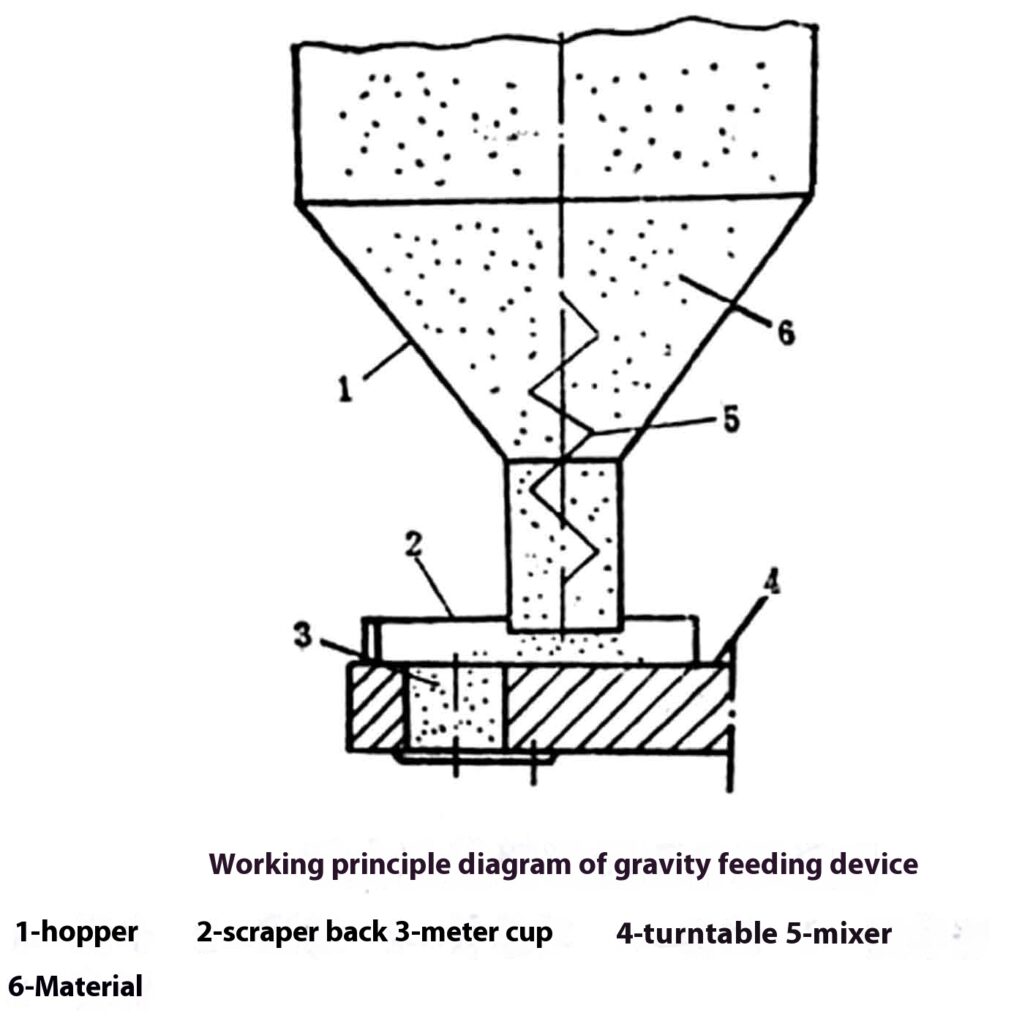
The gravity feed system utilizes the principle that goods can flow from high to low under the influence of gravity. The goods are placed at a high position and flow through the fixed material channel to the low position, thereby feeding the goods. When goods flow through the material chute, an arch or bridge can easily form, which can lead to poor flow or even blockages. Therefore, the flow chute must be smooth and flat, and the necessary anti-blocking devices must be installed. For goods with orientation requirements, a sorting and orientation device must also be installed. Goods that are not suitable for automatic orientation must be manually placed and stacked in the hopper beforehand.
The figure shows a diagram of the operating principle of the gravity-fed feeder for powdered and granular materials. The material in hopper 1 flows continuously toward the quantitative rotary disc 4 under the influence of its own weight and the agitator 5, and the fixed scraper 2 scrapes the excess material off the rotating disc metering cup 3, thereby performing the metering operation.
Piece-Feed Device
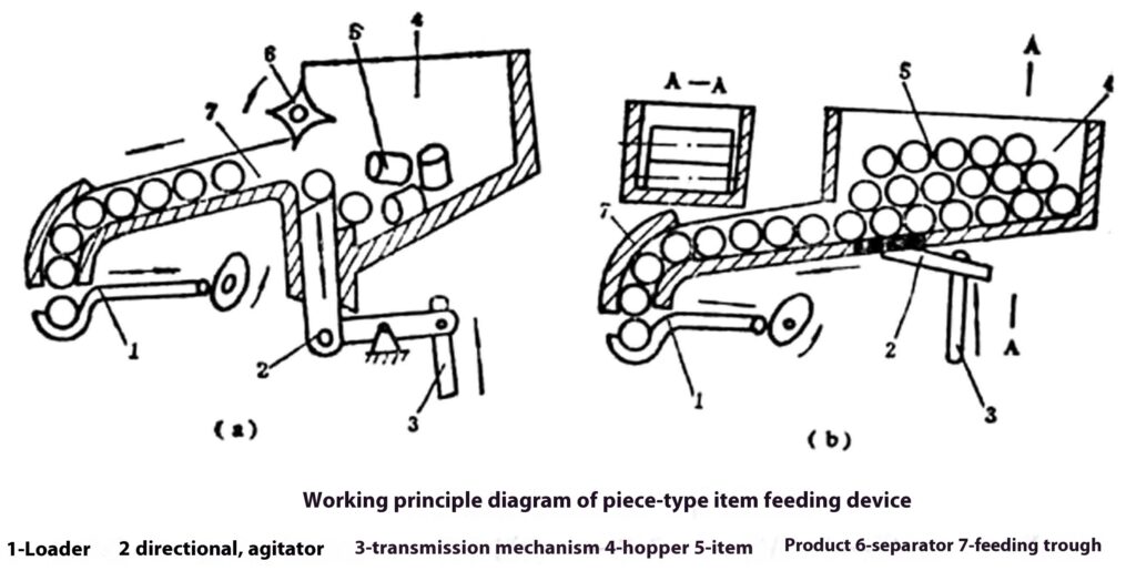
The figure shows a schematic diagram of the piece-good feeding device. Figure (a) shows a piece-good feeding device capable of automatic selection and orientation, and suitable for the automatic feeding of cylindrical pieces with relatively small lengths and diameters. The unordered pieces of material are stored in the hopper. Under the action of the orientation mechanism 2 and the ejector 6, the pieces of material are arranged in a specific direction in the feed chute 7 and move through the feed chute to the feed inlet 1 under the influence of their own weight, resulting in an intermittent feed of the pieces. Figure (b) shows a feeding device for pieces with relatively large lengths and diameters that cannot be easily selected and oriented automatically. The pieces of material must first be manually arranged in the hopper. Under the influence of the weight of the material pieces and the action of the agitator 2, the material pieces move via the feed chute 7 to the feed inlet 1, after which the feed inlet transports the pieces to the next process.
Tire Supply
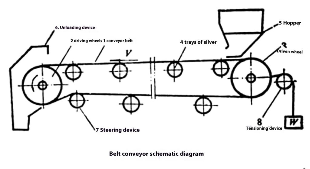
The conveyor system can be used to transport bulk, block, bagged, and general cargo, and can consist of multiple conveyors to meet the various requirements of the packaging process.
The figure shows a schematic diagram of the conveyor belt. The goods are transported from hopper 5 to the unloading device 6 and unloaded. The tensioning device 8 is used to adjust the tension of the belt, and the guide roller 7 is used to increase the wrap angle to ensure the belt’s conveying capacity.
The conveyor belt in the belt feed system comes into contact with the goods. Depending on the physical and chemical properties and hygiene requirements of the goods, the appropriate belt material must be selected and the necessary physical and chemical treatments must be performed. Conveyor belts include, among others, cotton canvas, synthetic fiber fabrics, rubber canvas, nylon sheet, steel, metal mesh, etc. Common physical and chemical treatment methods for conveyor belts include impregnation, coating with surface-protective layers, etc.
Chain Feeder
The figure shows a schematic diagram of a chain conveyor used to transport toothpaste on a toothpaste cartoning machine. The basic structure of a chain conveyor, which is commonly used to feed packaged items, is shown in the figure. The drive mechanism for transporting items consists of two parallel ring chains. The two chains are connected by a small shaft or a slat to keep the two chains parallel and at an equal distance from each other. Special chain plates are mounted on the chain, or rollers and pallets are mounted on the small shaft (slat) between the two chains. Accessories such as push plates are used to move the packaged items forward. The traction chain generally uses a standard bushing roller chain, or a bushing roller chain with a special long chain plate, a flat chain, etc. To ensure proper meshing between the chain and the sprocket teeth, as well as the positional accuracy of the feed, a chain tensioner is usually required.
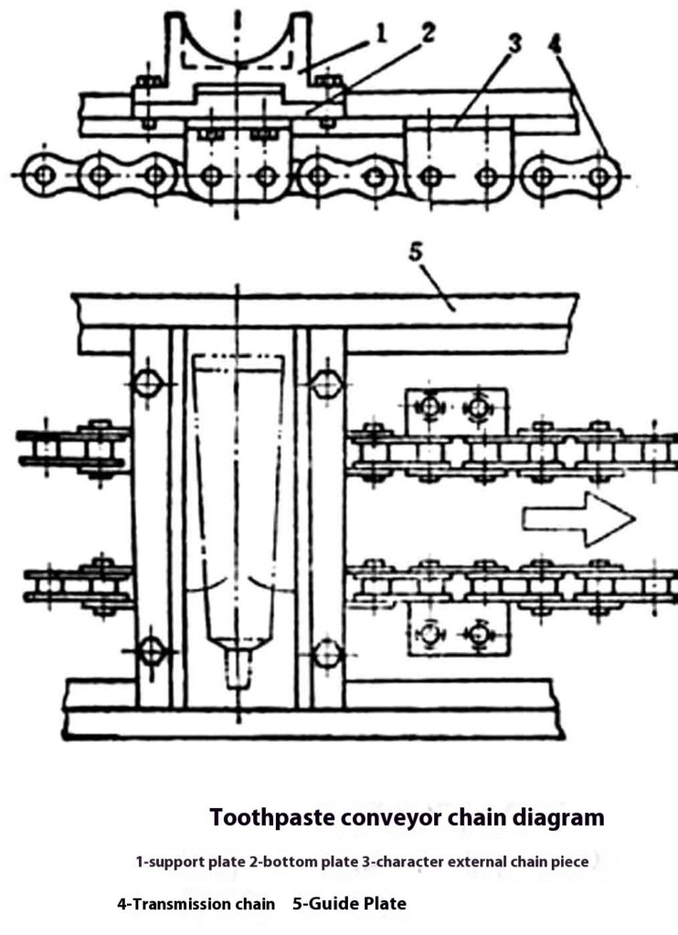
Chain conveyors are suitable for handling pieces and stalks where precise delivery of packaged items and specific packaging operations during transport are required.
Rotary Disc Feeder
When the rotating disc spins, the materials stored in the disc hopper are moved toward the outer edge of the rotating disc by friction and centrifugal force; they are arranged in a single direction along the tangent to the disc and enter the conveyor channel, tangent to the outer edge of the disc. By installing a specific conveying device on the conveying channel, automatic sorting and targeted arrangement of materials can be achieved.
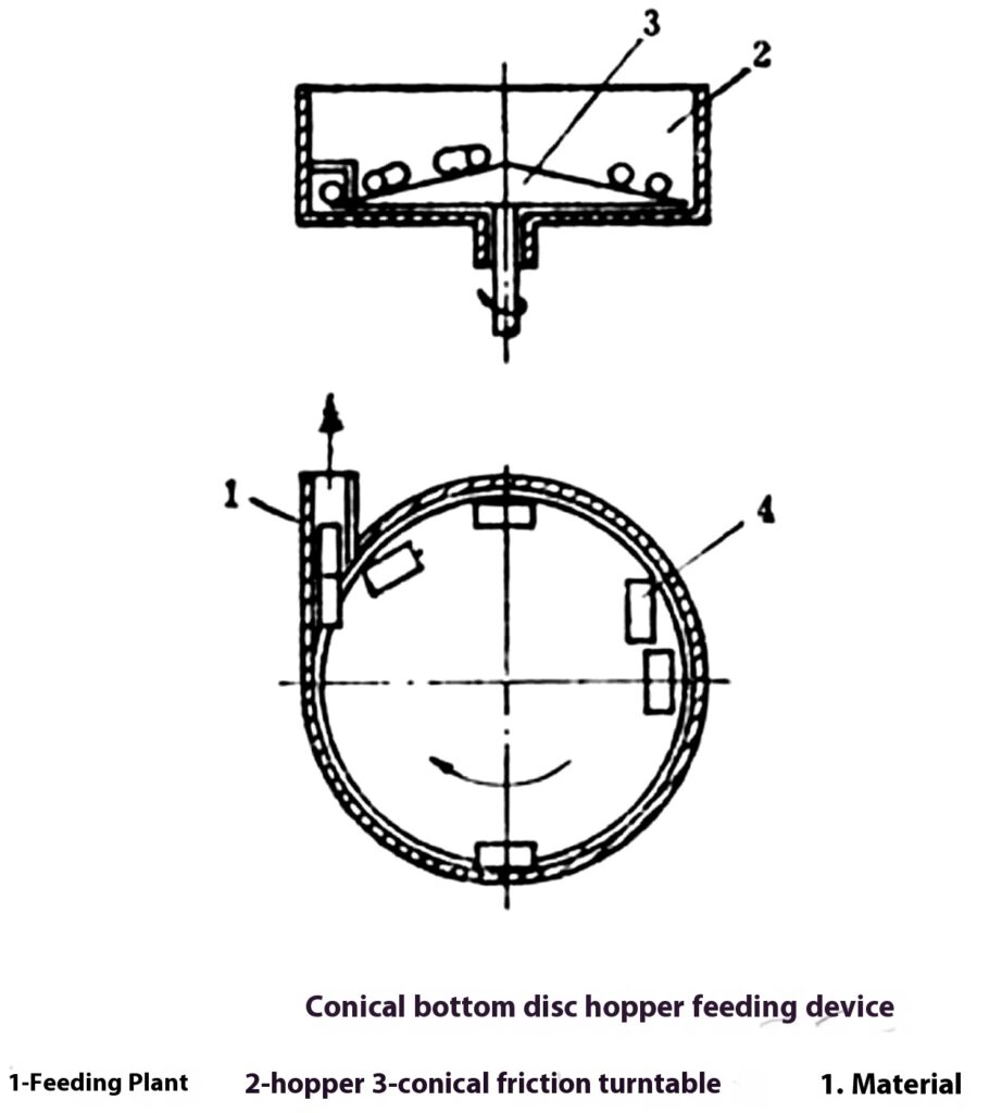
The illustration shows how the feed mechanism with a conical bottom disc works. The conical bottom disc can increase the tendency of materials to move toward the outer edge of the rotating disc. The materials are arranged in a single direction along the tangent to the disc and, in turn, enter the conveyor chute. This device has a simple structure and reliable operation. It is suitable for the automatic sorting and directed feeding of various small columns, tubes, lids, blocks, and sheet materials.
Electromagnetic Vibrating Feeder
A vibrating conveyor is a device that uses vibration technology to transport loose powders and small objects over short and medium distances. Depending on the structure of the vibrating body, it can be classified into a straight trough type and a disc hopper type; depending on the type of excitation source, it can be classified into a mechanical type, an electromagnetic type, a hydraulic type, and a pneumatic type. Here, we will primarily introduce the electromagnetic vibrating conveyor.
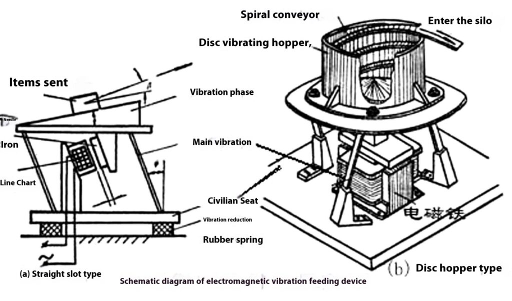
The structure of the electromagnetic vibrating chute generally consists of exciting electromagnets, armatures, vibrating bodies, main vibration springs, vibration-damping springs, and bases. As shown in the figure, the vibrating chute body (or hopper) is supported on the base by the main vibration plate spring; the iron core and coil of the electromagnet are mounted on the base, and the armature is attached to the bottom of the vibrating body; there is an angle between the working surface of the vibrating trough body and the horizontal plane (there is a spiral-shaped conveying channel with a spiral angle of α inside the vibrating hopper), and there is also an angle between the main vibrating plate spring and the vertical plane. The entire unit is connected by bolts, vibration-damping springs, and the frame.
Of course, the principles behind the disc-funnel type and the straight trough type are essentially the same, except that the straight trough conveying channel has been replaced by a spiral conveying channel, and the swivel vibration has been replaced by torsional vibration.
Take the vibrating trough feeder as an example to illustrate how it works.
As shown in Figure (a), the object is placed in the trough. The trough vibrates in one direction under the influence of electromagnetic excitation force and the spring of the main vibration plate. When the trough moves toward the upper right, the object is propelled by the frictional force of the trough and accelerates toward the upper right. When the trough decelerates toward the upper right or accelerates toward the lower left under the influence of an electromagnetic attractive force, the object—having acquired a certain amount of kinetic energy during its acceleration toward the upper right— it still tends to continue moving upward and to the right, or to shift a certain distance to the right relative to the chute’s working surface, or even to make a diagonal throw upward and to the right and then fall back onto the chute’s working surface. When the chute moves upward and to the right again, the object is once more accelerated by friction, and the above motion cycle repeats itself. In this way, each time the tank body moves back and forth once and vibrates, the item moves a certain distance to the right relative to the corresponding tank body, thereby meeting the requirement for delivering items.
Vacuum machine
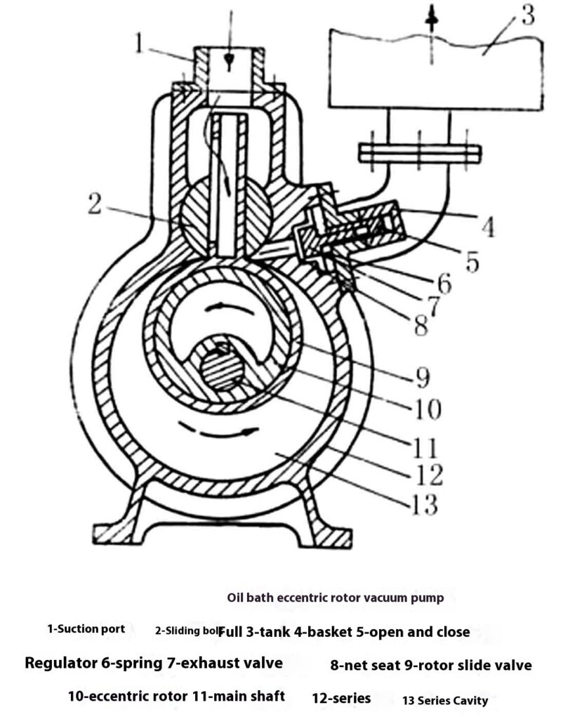
The vacuum pump is the most important component of the vacuum packaging machine, and its performance directly affects the vacuum level. There are two main types of vacuum pumps used in vacuum packaging machines: one is a vacuum pump with an eccentric rotor in an oil bath (also known as a sliding-valve vacuum pump); the other is a vacuum pump with rotating vanes in an oil bath. As shown in the figure.
Oil-bath eccentric rotor vacuum pump
Principle of Operation: As shown in the figure. A rotary slide valve 9 is installed in pump 12; it consists of a valve ring and a valve stem. The valve ring on the rotary slide valve is secured to the eccentric rotor 10 via a sleeve, and the geometric center of the rotating shaft 11 and the pump chamber 13 coincide. The valve stem at the top of the rotor slide valve can move freely up and down within the cylindrical slide bolt 2 and pivot left and right. The valve ring sleeve slides along the surface of the pump chamber 13. When the shaft 11 rotates counterclockwise, the rotor slide valve 9 divides the pump chamber 13 into two working chambers, and the volume of chamber A gradually increases, while the volume of chamber B gradually decreases. The gas pressure in chamber A continues to decrease, and the pumped gas enters chamber A through the cavity in the valve stem and the rectangular hole on the side. When the rotary slide valve rotates to the top dead center of pump chamber 13, the suction phase ends and chamber A reaches its maximum suction volume, after which the rectangular hole is closed. The pump shaft 11 continues to rotate, and the volume of the original working chamber gradually begins to decrease again; the gas is compressed, and the pressure continues to rise. When the spring pressure of the discharge valve 7 is exceeded, the gas pushes it open and is discharged. The two chambers, A and B, operate alternately. When chamber A inhales, chamber B exhales. Each rotation of the pump shaft corresponds to the completion of one suction and exhaust cycle.
Oil-bath rotary vane vacuum pump
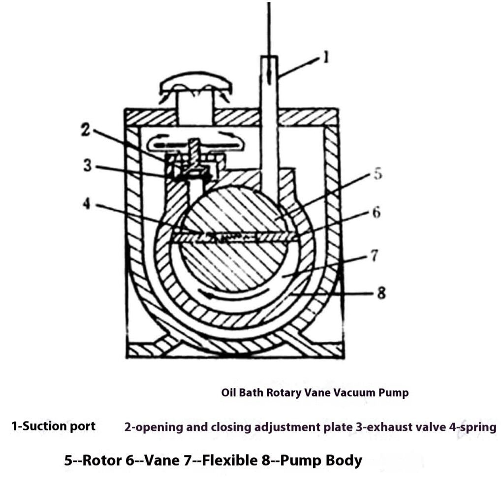
Principle of operation: as shown in the figure. When the eccentric rotor 5, equipped with two vanes 6, rotates clockwise, vane G, under the pressure of spring 4 and its own centrifugal force, presses against the inner wall of the pump housing 8, causing the right suction chamber to expand further and allowing the pumped gas to enter through suction port l. When the other vane passes the suction port, the drawn-in gas is isolated, and the suction process is complete. The rotor continues to rotate; the isolated gas is gradually compressed, and the pressure increases. When the pressure exceeds the pressure at discharge valve 3, the gas pushes discharge valve 3 open via the discharge pipe and is discharged from the pump through the oil and the discharge port. During pump operation, the vanes always divide the pump chamber into two working chambers, A (suction) and B (discharge). Each time the eccentric rotor completes one revolution, two suction and discharge cycles occur.
Conclusion
In the packaging process, feeding systems play a crucial role in ensuring the smooth and efficient transfer of materials to dosing equipment for packaging. The various types of feeding systems—such as gravity feed, belt feed, chain conveyors, vibrating chutes, and rotary disc conveyors—are designed to meet the diverse requirements of different materials and packaging processes. These systems must be tailored to the physical and chemical properties of the products being conveyed to ensure reliability and prevent issues such as blockages or misalignment.
In addition, vacuum pumps—such as the oil-bath eccentric rotor pump and the rotary vane pump—are integral components of vacuum packaging machines. They ensure the proper vacuum level for preserving products. Selecting the right supply and vacuum equipment ensures efficient, reliable, and safe packaging, which is essential for meeting both production and quality standards.






 English
  Dutch
Dutch